


Colecovision Controller Atari Phoenix Control Pad Joystick Open Source PCB Only
Original price
$19.95
-
Original price
$19.95
Original price
$19.95
$19.95
-
$19.95
Current price
$19.95
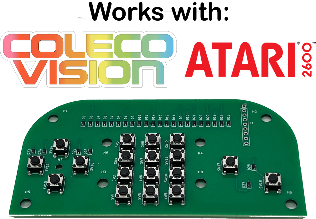
This PCB was inspired by the Open Source Colecovision controller project started by Sparkletron.
I have contributed to the project and have now made my changes available for download and use.
Please note: These resources are intended for users with experience in 3D printing and using a soldering iron to attach 7 wires. RetroGameBoyz does not offer support for these processes. However, I am happy to provide you with a completed, PCB with surface mounted diodes and preassembled micro-switches. If you want a completed, plug and play controller, see my other products.
-
Fully tested and operational when assembled
Just solder a 9 pin DB9 joystick cable (sold separately) - Returns not accepted on PCBs - you want return guarantees? See my completed controllers.
Assembly Instructions (see pics)
Download 3D Model Files
Cable length should be cut to 4 to 5 feet or less before assembly. Note that, longer cables can causes some games to respond in an unexpected manner. (For example, Defender will activate smart bomb when button 1 (laser) is fired and the ship is moving right or left. This is a Colecovision console behavior)
- Required: DB9 9 wire joystick cable (sold separately)
- Cut about 2 1/2 inches of sheathing from the DB9 cable to expose 9 wires
- Test continuity of each wire to match with each pin number
(You will not use wire for pin 7 or pin 9) - Solder each wire to appropriate pin through hole on PCB as indicated
- Attached PCB to 3D printed base bottom enclosure (snaps over standoffs)
- Insert keypad number buttons, fire buttons and Dpad in top enclosure
- With Top enclosure facing down, gently curve wire into wire restraint where indicated
- Place bottom cover over top
- Secure with screws
- 5/8th inch long at most
- #4 screw 0.112 inch diameter
- Course thread (sheet metal type)
- Pan Head no larger then 3/16th of an inch